Defining Boundary Conditions
Define boundary conditions. You can define boundary conditions with "BoundaryCondition" element. Boundary conditions are not required.
Add definition of "Boundary Condition" to the solver definition file you created, as shown in List 5. The added part is shown with highlight.
 1(abbr.)
 2  </GridRelatedCondition>                                                  |
 3  <BoundaryCondition name="inflow" caption="Inflow" position="node">
 4    <Item name="Type" caption="Type">
 5      <Definition valueType="integer" default="0" >
 6        <Enumeration value="0" caption="Constant" />
 7        <Enumeration value="1" caption="Variable" />
 8      </Definition>
 9    </Item>
10    <Item name="ConstantDischarge" caption="Constant Discharge">
11      <Definition valueType="real" default="0">
12        <Condition type="isEqual" target="Type" value="0"/>
13      </Definition>
14    </Item>
15    <Item name="FunctionalDischarge" caption="Variable Discharge">
16      <Definition conditionType="functional">
17        <Parameter valueType="real" caption="Time"/>
18        <Value valueType="real" caption="Discharge(m3/s)"/>
19        <Condition type="isEqual" target="Type" value="1"/>
20      </Definition>
21    </Item>
22  </BoundaryCondition>
23</SolverDefinition>
Now make sure that solver definition file is arranged correctly.
Launch iRIC, and start a new project with solver "Sample Solver". When you create or import a grid, the [Pre-processing Window] will become like Figure 14. When you do now know how to create or imprt a grid, refer to the User Manual.
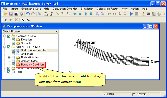
Figure 14 The [Pre-processing Window] after creating a grid
Click on [Add new Inflow] on the context menu on [Boundary Condition] node, and The [Boundary Condition] dialog (Figure 15) will open, and you can define boundary condition on this dialog.
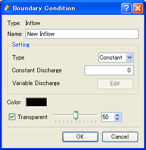
Figure 15 The [Boundary Condition] dialog
When you have finished defining boundary condition, click on [OK]. Drag around the grid nodes to select nodes, and click on [Assign Condition] in the context menu. Figure 16 shows an example of a grid with boundary condition.
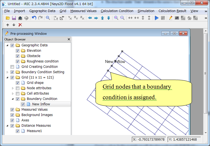
Figure 16 Example of a grid with boundary condition
What it comes down to is:
Boundary condition is defined Grid attribute is defined with "Item" element under "GridRelatedCondition" element.
The structure under "Item" element is the same to that for calculation condition.