Defining Grid attributes
Define grid attributes. Grid attributes are defined with "GridRelatedCondition" element. Add definition of grid related condition to the solver definition file you created, as shown in List 4. The added part is shown with highlight.
 1(abbr.)
 2  </CalculationCondition>
 3  <GridRelatedCondition>
 4    <Item name="Elevation" caption="Elevation">
 5      <Definition position="node" valueType="real" default="max" />
 6    </Item>
 7    <Item name="Obstacle" caption="Obstacle">
 8      <Definition position="cell" valueType="integer" default="0">
 9        <Enumeration value="0" caption="Normal cell" />
10        <Enumeration value="1" caption="Obstacle" />
11      </Definition>
12    </Item>
13    <Item name="Rain" caption="Rain">
14      <Definition position="cell" valueType="real" default="0">
15        <Dimension name="Time" caption="Time" valueType="real" />
16      </Definition>
17    </Item>
18  </GridRelatedCondition>
19</SolverDefinition>
Now make sure that solver definition file is arranged correctly.
Launch iRIC, and starts a new project with solver "Sample Solver". Now you will see the [Pre-processing Window] like in Figure 10. When you create or import a grid, the [Pre-processing Window] will become like in Figure 11.
When you do not know how to create or import a grid, refer to the User Manual.
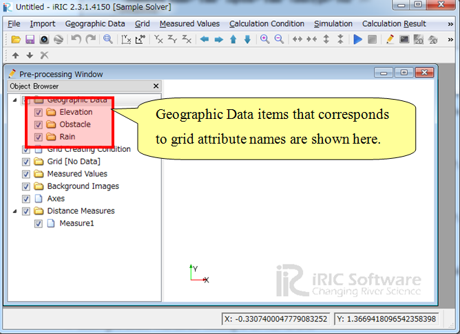
Figure 10 The [Pre-processing Window]
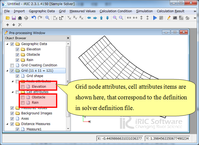
Figure 11 The [Pre-processing Window] after creating a grid
When you edit the grid attribute "Elevation" with the following procedure, the [Edit Elevation] dialog (Figure 12) will open, and you can check that you can input real number as "Elevation" value.
Select [Grid] –> [Node attributes] –> [Elevation] in the [Object Browser].
Select grid nodes with mouse clicking in the canvas area
Show context menu with right-clicking, and click on [Edit].
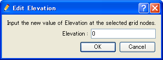
Figure 12 The [Edit Elevation] dialog
When you do the same operation against attribute "Obstacle" to edit "Obstacle" value, the [Obstacle edit dialog] (Figure 13) will open, and you can check that you can select obstacle values from that you defined in solver definition file, in List 4.
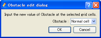
Figure 13 The [Obstacle edit dialog]
What it comes down to is:
Grid attribute is defined with "Item" element under "GridRelatedCondition" element.
The structure under "Item" element is basically the same to that for calculation condition, but there are different points:
You have to specify "position" attribute to determine whether that attribute is defined at nodes or cells.
You can not use types "String", "Functional", "File name" and "Folder name".
You can not define dependency.
You can define dimension of the attribute, using "Dimension" element.
For grid attributes, iRIC defines some special names. For attributes for certain purposes, you should use those names. Refer to Special names for grid attributes and calculation results for the special grid attribute names.