Defining calculation conditions
Define calculation conditions. Calculation conditions are defined in "CalculationCondition" element. Add description of calculation condition to the solver definition file you created in Defining basic information . Solver definition file content is now as shown in List 2. The added part is shown with highlight.
 1<?xml version="1.0" encoding="UTF-8"?>
 2<SolverDefinition
 3  name="samplesolver"
 4  caption="Sample Solver"
 5  version="1.0"
 6  copyright="Example Company"
 7  release="2012.04.01"
 8  homepage="http://example.com/"
 9  executable="solver.exe"
10  iterationtype="time"
11  gridtype="structured2d"
12>
13  <CalculationCondition>
14    <Tab name="basic" caption="Basic Settings">
15      <Item name="maxIteretions" caption="Maximum number of Iterations">
16        <Definition valueType="integer" default="10">
17        </Definition>
18      </Item>
19      <Item name="timeStep" caption="Time Step">
20        <Definition valueType="real" default="0.1">
21        </Definition>
22      </Item>
23    </Tab>
24  </CalculationCondition>
25  <GridRelatedCondition>
26  </GridRelatedCondition>
27</SolverDefinition>
At this point, the structure of the solver definition file is as shown in Figure 5.
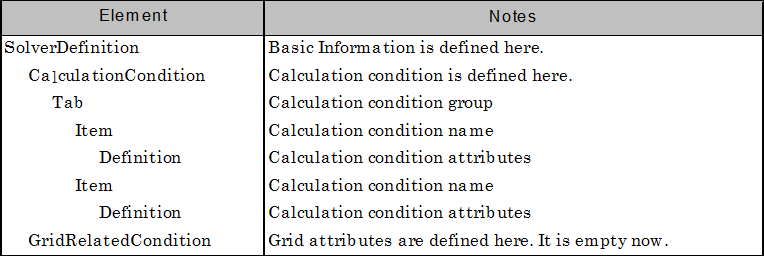
Figure 5 Solver definition file structure
Now make sure that solver definition file is arranged correctly.
Launch iRIC. The [iRIC Start page] dialog (Figure 3) will open, so please click on [Create New Project], select "Sample Solver" from the list, and click on [OK]. The Warning dialog (Figure 6) will be open, so click on [OK].
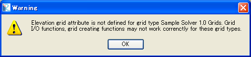
Figure 6 The [Warning] dialog
The [Pre-processing Window] will open, so perform the following:
Menu bar: –> [Calculation Condition] (C) –> [Setting] (S)
The [Calculation Condition] dialog (Figure 7) will open. Now you can see that the calculation condition items you defined in List 2 are shown.
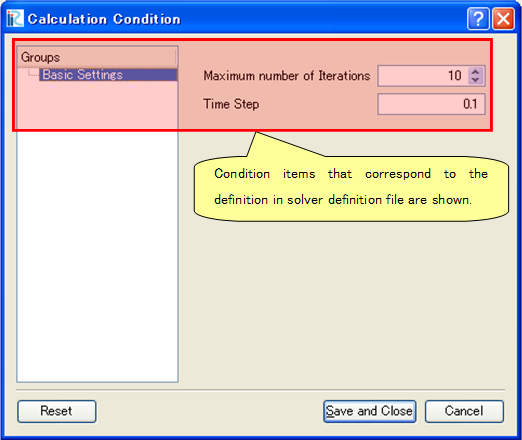
Figure 7 The [Calculation Condition] dialog
Now add one more group and add calculation condition items. Add "Water Surface Elevation" Tab element just after "Basic Settings" Tab element. List 3 shows the solver definition file that has definition of "Water Surface Elevation" Tab. The added part is shown with highlight.
 1(abbr.)
 2    </Tab>
 3    <Tab name="surfaceElevation" caption="Water Surface Elevation">
 4      <Item name="surfaceType" caption="Type">
 5        <Definition valueType="integer" default="0">
 6          <Enumeration caption="Constant" value="0" />
 7          <Enumeration caption="Time Dependent" value="1" />
 8        </Definition>
 9      </Item>
10      <Item name="constantSurface" caption="Constant Value">
11        <Definition valueType="real" default="1">
12          <Condition type="isEqual" target="surfaceType" value="0"/>
13        </Definition>
14      </Item>
15      <Item name="variableSurface" caption="Time Dependent Value">
16        <Definition valueType="functional">
17          <Parameter valueType="real" caption="Time(s)"/>
18          <Value valueType="real" caption="Elevation(m) "/>
19          <Condition type="isEqual" target="surfaceType" value="1"/>
20        </Definition>
21      </Item>
22    </Tab>
23  </CalculationCondition>
24  <GridRelatedCondition>
25  </GridRelatedCondition>
26</SolverDefinition>
At this point, the structure of the solver definition file is as shown in Figure 8.
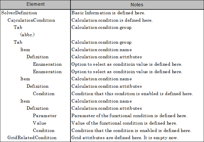
Figure 8 Solver definition file structure
Now make sure that solver definition file is arranged correctly. Do the operation you did again, to open The [Calculation Condition] dialog (Figure 9).
Now you can see that the new group "Water Surface Elevation" is added in the group list. You'll also notice that the "Constant Value" item is enabled only when "Type" value is "Constant", and the "Time Dependent Value" item is enabled only when "Type" value is "Time Dependent".
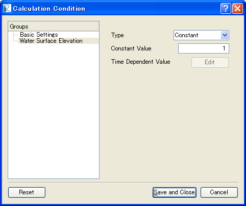
Figure 9 The [Calculation Condition] dialog
What it comes down to is:
Calculation condition group is defined with "Tab" element, and calculation condition item is defined with "Item" element.
The Structure under "Definition" elements depends on the condition type (i. e. Integer, Real number, functional etc.). Refer to Examples of calculation conditions, boundary conditions, and grid generating condition for examples of calculation condition items for each type.
Dependenciy between calculation condition items can be defined with "Condition" element. In "Condition" element, define the condition when that item should be enabled. Refer to Example of condition to activate calculation conditions etc. for examples of "Condition" element.
In this example, the calculation condition dialog shows the items as a simple list, but iRIC has feature to show items with more complex layouts, like layout with group boxes. Refer to Example of dialog layout definition for more complex layouts.