Adding codes to output a grid
Adds codes to output grid.
First, add codes to output a very simple grid, to check whether the program works together with iRIC successfully.
List 20 shows the source code with lines to output grid. The added lines are shown with highlight.
 1program SampleProgram
 2  use iric
 3  implicit none
 4
 5  integer:: fin, ier
 6  integer:: icount, istatus
 7  integer:: imax, jmax
 8  double precision, dimension(:,:), allocatable::grid_x, grid_y
 9  character(200)::condFile
10
11  icount = nargs()
12  if ( icount.eq.2 ) then
13    call getarg(1, condFile, istatus)
14  else
15    stop "Input File not specified."
16  endif
17
18  ! Opens grid generating data file.
19  call cg_iric_open(condFile, IRIC_MODE_MODIFY, fin, ier)
20  if (ier /=0) stop "*** Open error of CGNS file ***"
21
22  imax = 10
23  jmax = 10
24
25  ! Allocate memory for creating grid
26  allocate(grid_x(imax,jmax), grid_y(imax,jmax)
27
28  ! Generate grid
29  do i = 1, imax
30    do j = 1, jmax
31      grid_x(i, j) = i
32      grid_y(i, j) = j
33    end do
34  end do
35
36  ! Outputs grid
37  cg_iric_write_grid2d_coords(fin, imax, jmax, grid_x, grid_y, ier)
38
39  ! Closes grid generating data file.
40  call cg_iric_close(fin, ier)
41end program SampleProgram
When it was compiled successfully, copy the executable file to the folder you created in Creating a folder, and rename it into the name you specified as [executable] attribute in Defining basic information. This time, rename into "generator.exe". Copy the DLL files into that folder, that is need to run the grid generating program.
Now check whether the grid generating program can be launched from iRIC successfully.
Starts a new project with solver "Nays2DH", and select "Sample Grid Creator" as the grid generating algorithm like in Defining basic information. The [Grid Creation] dialog (Figure 36) will open.
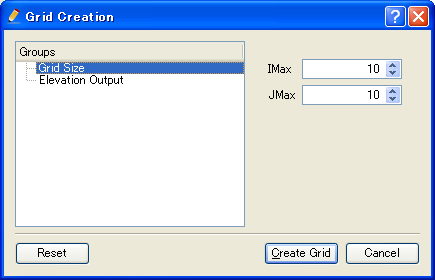
Figure 36 The [Grid Creation] dialog
Click on [Create Grid], and a 10 x 10 grid will be created and loaded on the pre-processing window (Figure 37).
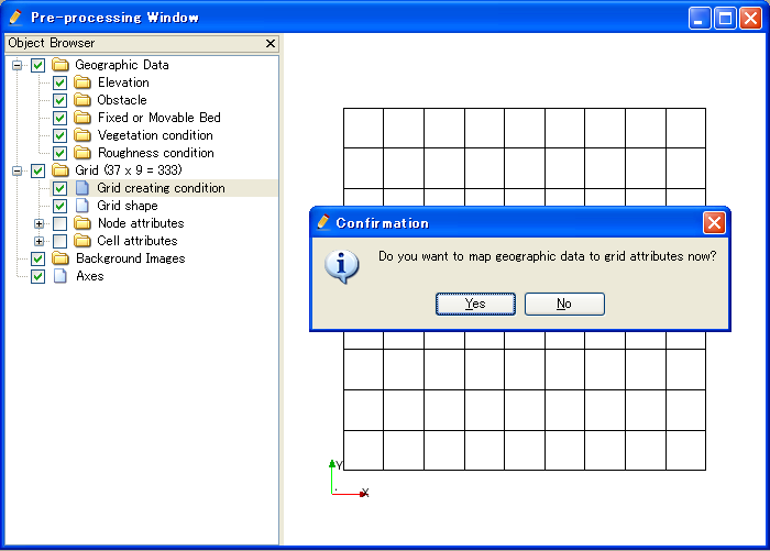
Figure 37 The pre-processing window after creating grid
Refer to Outputting calculation grids for the detail of subroutines to output grids. Note that in Outputting calculation grids the subroutines to output three-dimensional grids are listed, but they can not be used in grid generating programs. In grid generating programs, only subroutines to output two-dimensional grids can be used.