Structure
Structures of solver definition files, grid generating program definition files are described in this section.
Solver definition file
Structure of solver definition files for a solver that uses only one calculation grids is shown in Figure 45, and that for a solver that uses multiple types of calculation grids is shown in Figure 46, respectively.
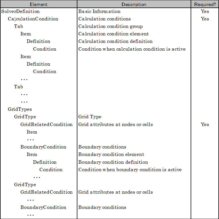
Figure 45 Structure of solver definition file
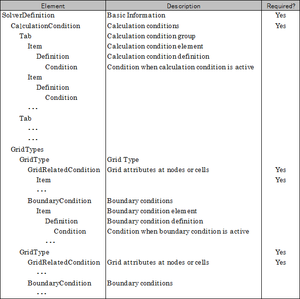
Figure 46 Structure of solver definition files for a solver that uses multiple grid types
When the solver uses multiple types of grids, Solver developers should add multiple GridType elements, and defines grid structure, grid attributes, and boundary conditions under each GridType element.
An example of solver definition file for a solver that uses multiple grid types, is shown in List 25. In this example, boundary condition definition is dropped, because that is not required. Please pay attention that the following point is different:
Grid structure (gridtype attribute) is not definied in SolverDefinition elemenet, but in GridType elements.
When a user creates a new project and selects a solver that bundles the solver definition shown in List 25, a new pre-processor in Figure 47 is shown.
 1<?xml version="1.0" encoding="UTF-8"?>
 2<SolverDefinition
 3  name="multigridsolver"
 4  caption="Multi Grid Solver"
 5  version="1.0"
 6  copyright="Example Company"
 7  release="2012.04.01"
 8  homepage="http://example.com/"
 9  executable="solver.exe"
10  iterationtype="time"
11>
12  <CalculationCondition>
13    <!-- Define calculation conditions here. -->
14  </CalculationCondition>
15  <GridTypes>
16    <GridType name="river" caption="River">
17      <GridRelatedCondition>
18        <Item name="Elevation" caption="Elevation">
19          <Definition valueType="real" position="node" />
20        </Item>
21        <Item name="Roughness" caption="Roughness">
22          <Definition valueType="real" position="node"/>
23        </Item>
24        <Item name="Obstacle" caption=" Obstacle">
25          <Definition valueType="integer" position="cell"/>
26        </Item>
27      </GridRelatedCondition>
28    </GridType>
29    <GridType name="floodbed" caption="Flood Bed">
30      <GridRelatedCondition>
31        <Item name="Elevation" caption="Elevation">
32          <Definition valueType="real" position="node" />
33        </Item>
34      </GridRelatedCondition>
35    </GridType>
36  </GridTypes>
37</SolverDefinition>
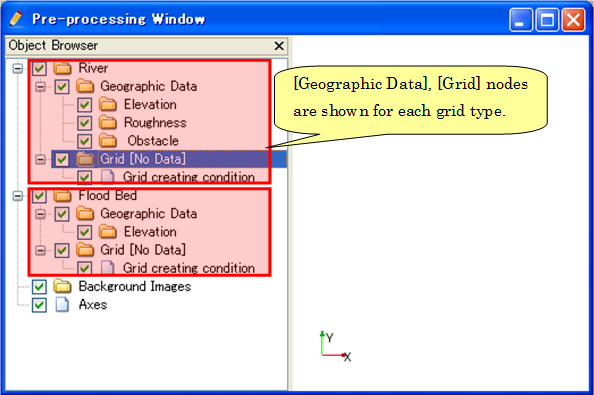
Figure 47 Pre-processor image after loading the solver definition file with multiple grid type definitions
Grid generating program definition file
Structure of grid generating program definition file is shown in Figure 48
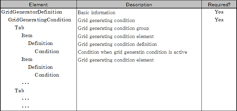
Figure 48 Structure of grid generating program definition file